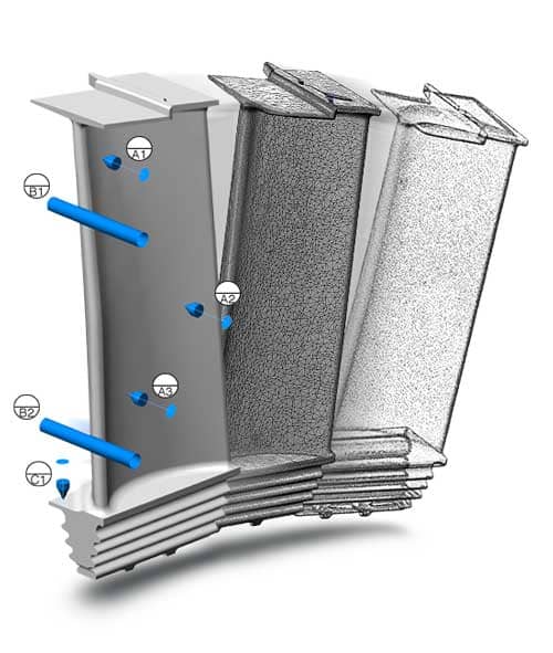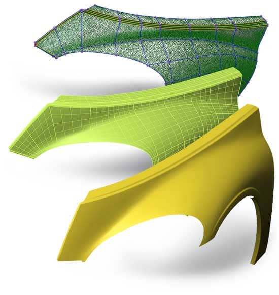
3D Laser Scanning is now being implemented in a variety of fields and industries as a fast and cost effective solution for measuring, inspection and Reverse Engineering applications. 3D laser scanning is ideally suited for measuring and inspecting fine detail. complex geometries, and multi contoured surfaces. Many times these fine details or free-form surfaces would require large data set to accurately capture the existing condition of an object. This is especially true where performing such an inspection via traditional methods is impractical or ineffective. Where as traditional means may have included height gauges, no-go gauges, calipers or micrometers this new technology is able to encompass all of these into one system. Some of the industries currently using our services and 3D Scanning technology include Automotive, Manufacturing, Product development and Tool & Die to name a few.
3D scanning is a non-destructive technology that can be used for non-contact measuring using a Laser Line scanner or through contact probing with a probe point. This technology digitally captures real-world conditions of a part by recording its exact shape and size. While recording, it is generating a 3D representation in space to be used for a variety of quantitative and qualitative measurements.
3D Scanners measure surface geometry, Free-form geometry and fine details to generate a highly accurate point cloud.
Point clouds are produced by 3D scanners or probe points, which measure many points on the external surface of an object. A point cloud is a set of data points in space that represent the 3D object or shape being scanned. Each point has its own set of X,Y,Z coordinates that in turn make up the point cloud.
What is the 3D Laser Line Scanning Process?
- Ensure the part is clean and free of any debris, it is important to note that any oil, residue or debris will more than likely show up on your scan data.
- Depending on the reflectivity of the part, it may be recommended to use a dulling spray or developer to ensure proper data capture. Please note that over spraying or inconsistent application can result in poor or inaccurate data capture.
- It is important to ensure you are not only scanning in a suitable environment conducive to 3D scanning but are also placing the part on a suitable work surface such as a granite surface table or fixture.
- Assuming the scanner has already been calibrated and verified and the appropriate setting applied for your specific application scanning can now commence.
- If probing is required due to line of sight limitations or increased accuracy requirements ensure that the part does not deflect or move while probing.
- Most software’s now a days are able to polygonize data as you scan but in the case yours cannot or you are using a structured light scanner it may be required for you to pre-align your data set and then manually configure your settings to polygonize.
- This refers to ‘shaking’ and ‘uniquing’ the data to remove any outliers and extraneous or duplicate data points. Once, completed you are left with the final mesh.
- From the Mesh, features such as planes, cylinders, cones, circles etc. can be extracted for Quality Inspection or Reverse Engineering purposes.
- Meshes can be exported in a variety of formats such as .STL, .OBJ, .PLY or .IGES but are typically .STL.
- Features can be exported as .IGES format
Quality Inspection or Reverse Engineering?

Once the Mesh has been created it can now be used for Quality Inspection purposes. This involves importing the existing CAD (Nominal) and overlaying the Mesh (Measured) and measuring the deviation from the nominal to the measured components. If the CAD data is unavailable nominal features such as spheres, planes, cylinder etc. can be manually created and compared to the measured components. It is always recommended to inspect to CAD whenever possible because it ensures a more intrinsic inspection. The CAD model naturally allows to create ‘color map’ deviation reports, inspect features and apply GD&T callouts when required. When the inspection is completed a detailed .PDF report can be created which shows ‘color map’ screenshots, surface deviation points, report tables and feature callouts. These reports can be custom tailored to fit your required needs and also saved as a template for later use.
Using the Mesh and extracted features, it is possible to import this data set into parametric or NURBS modeling software to create a Reverse Engineered model. Some examples of these software’s are PolyWorks, Geomagic, NX, Catia, and SolidWorks to name a few. Depending on your requirements a solid model or NURBS model might be recommended. A solid model or idealized model is typically used for inspection purposes, CNC machining or manufacturing. Solid modeling assumes GD&T and corrects any imperfections in the model. It assumes that all planes are planar, parallel, and perpendicular and that Circles are concentric etc. Whereas, a NURBS model captures a true representation of the existing part and wraps a surface layer capturing any surface defects, free-form geometry and makes no assumptions for GD&T. NURBS modeling would typically be used for remachining, repair work, or custom work that requires knowing the exact existing surface. Both these forms of CAD can be used for CNC machining work or even Quality Inspection.